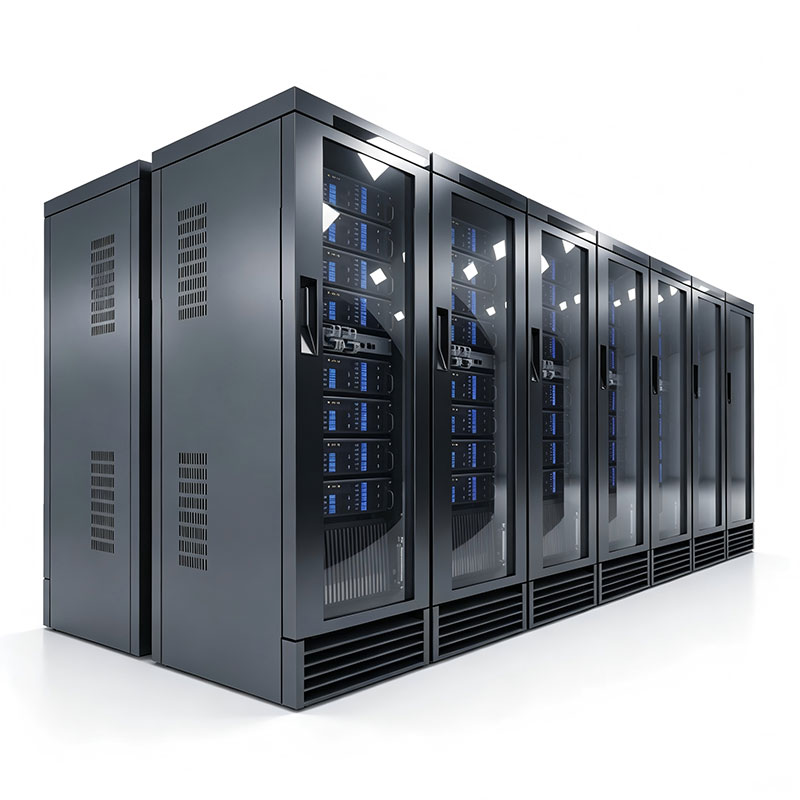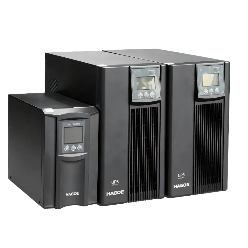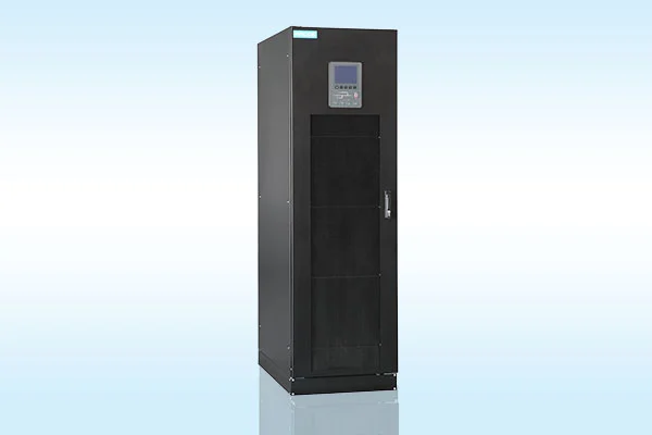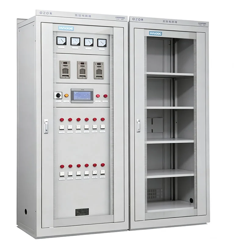
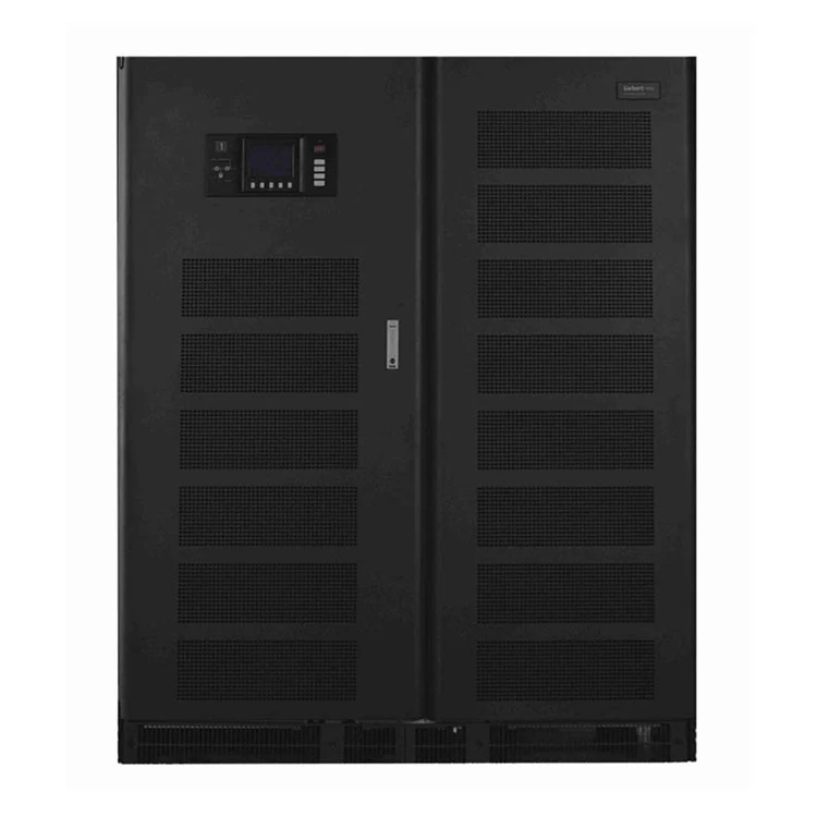
The core feature of a low-frequency UPS lies not only in its transformer but also in its combination of a low-frequency line-frequency transformer and an online double-conversion architecture.
The input AC power is first converted to DC by a rectifier; subsequently, the DC bus provides a stable intermediate power stage, which is then converted back to AC by the inverter for output to the load. During normal operation, the load is continuously powered by the inverter, rather than directly connected to the AC input.
The low-frequency transformer provides electrical isolation between the input and output circuits and enhances the system's ability to withstand inrush currents, nonlinear loads, and abnormal operating conditions.
This architecture makes low-frequency UPS systems particularly suitable for applications with extremely high requirements for equipment continuity and power quality—not just those requiring emergency battery backup.
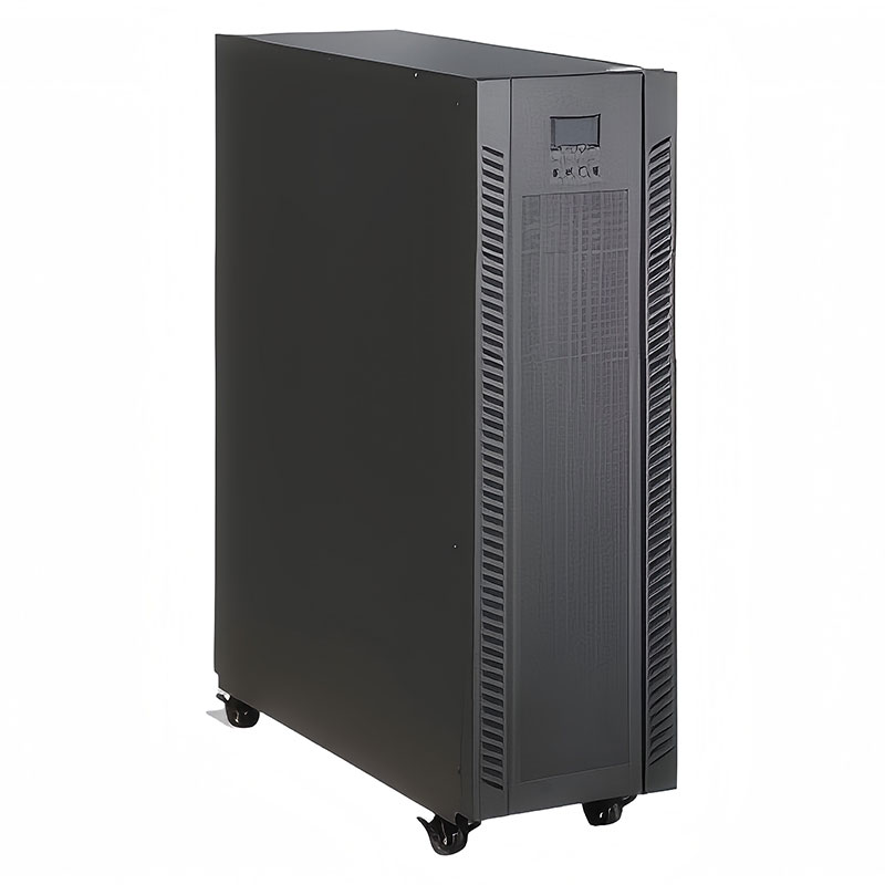
HAGOE Low Frequency UPS follows a typical online double-conversion power path:
AC Input → Rectifier → DC Bus → Inverter → Low-Frequency Transformer → Load
Under normal utility conditions, the rectifier supplies regulated DC power to the DC bus, while the inverter continuously supplies conditioned AC power to the load.
When the utility supply fails or falls outside the specified operating range, the battery system supplies energy to the DC bus and the inverter continues supplying the load. This eliminates the transfer interruption associated with conventional standby UPS architectures.
| Category | Technical Parameter | Specification |
|---|---|---|
| AC Input | Rated Capacity | 10 kVA / 15 kVA / 20 kVA / 30 kVA / 40 kVA / 60 kVA / 80 kVA / 100 kVA / 120 kVA / 140 kVA / 160 kVA / 200 kVA / 250 kVA / 300 kVA / 600 kVA / 1000 kVA / 1500 kVA / 2000 kVA |
| Working Mode and Principle | Online power static bypass switch (continuous switching), double-conversion technology, complete separation of power output | |
| Phase Number | Three phases + N + G | |
| Voltage | 380 V ±20% | |
| Frequency | 50 Hz ±10% | |
| Maximum Current | 19 A / 29 A / 38 A / 57 A / 76 A / 114 A / 158 A / 189 A / 227 A / 265 A / 303 A / 379 A / 473 A / 568 A / 1040 A / 1800 A / 2700 A / 3600 A | |
| Power Factor | 0.95 (with input filter) | |
| AC Bypass Input | Soft Start | 0–100% within 5 sec |
| Phase Number | Three phases + N + G | |
| Voltage | 380 V ±15% | |
| Frequency | 50 Hz ±2% | |
| Switching Time | 0 ms during overload | |
| Battery System | DC Voltage | 384 V (32 × 12 V batteries) |
| Floating Charge Voltage | 432 V | |
| Cut-off Voltage | 332 V | |
| Maximum Discharge Current | 25 A / 38 A / 51 A / 76 A / 101 A / 152 A / 203 A / 253 A / 304 A / 360 A / 425 A / 528 A / 660 A / 790 A / 1500 A / 2500 A / 3700 A / 5000 A | |
| Charging Current | 10–25 A (adjustable) | |
| AC Output | Phase Number | Three phases + N + G |
| Voltage | 380 V ±1% (steady-state load) | |
| Frequency | 50 Hz ±2% (mains power) / 50 Hz ±0.05% (battery power supply) | |
| Power Factor | 0.8 lagging | |
| Output Waveform | Sine wave | |
| Total Harmonic Distortion | ≤3% for linear load; ≤5% for nonlinear load | |
| Dynamic Load Voltage Transient | ±0.5% (from 0 to 100% load change) | |
| Instant Recovery Time | <10 ms (±0.5%) | |
| Unbalanced Voltage | ≤±3%; ≤±1% for balanced load voltage | |
| Overload Capacity | 120% for 10 min; 150% for 1 min (battery power supply) | |
| System Performance | Working Efficiency | >91%; 95% in ECO economic mode |
| Computer Communication Interface | RS232 / RS422 | |
| Operating Temperature | 0–40°C | |
| Relative Humidity | 0–90%, non-condensing | |
| Noise | 50 dB / 55 dB / 63 dB / 65 dB / 68 dB / 70 dB, depending on capacity | |
| Display | Type A: small LCD; Type B: large touchscreen display (120 × 90 mm) |
In a UPS system, the transformer is not used only for voltage conversion. It also contributes to electrical isolation, transient load handling, and system protection.
Industrial loads such as PLC systems, variable-frequency drives, motors, contactors, and large rectifier equipment can generate significant transient current during startup or dynamic operation. If UPS capacity is selected only according to steady-state active power, the inverter may experience overload, output voltage deviation, or unnecessary bypass operation.
The low-frequency transformer provides a robust magnetic and electrical interface with strong transient capability, giving the UPS greater design margin for applications with high starting current or impact loads.
| Engineering Factor | Low Frequency UPS | High Frequency UPS |
|---|---|---|
| Transformer | Low-frequency power transformer | High-frequency transformer / transformerless architecture |
| Electrical Isolation | Strong | Depends on system topology |
| Motor Starting Loads | More suitable | Requires careful sizing |
| Inrush Current | Higher tolerance | More sensitive to sizing |
| Nonlinear Loads | Suitable with proper configuration | Suitable with proper configuration |
| Industrial Applications | Strong fit | More suitable for general IT loads |
| System Weight | Relatively higher | Generally more compact |
| Installation Footprint | Larger | Smaller |
| Typical Priority | Robustness and isolation | Efficiency and compactness |
If a project primarily focuses on size, weight, and high power density, a high-frequency UPS may be more advantageous; however, if the project prioritizes isolation, surge load capacity, industrial environment adaptability, and long-term operational stability, a low-frequency UPS is generally a better choice.
Therefore, HAGOO does not recommend selecting a UPS based on the simplistic logic of "low-frequency is always better than high-frequency." Instead, it recommends configuring the UPS based on load type, power factor, startup current, backup time, and grid conditions.
UPS capacity should not be selected simply by adding the nameplate ratings of all connected equipment.
The engineering assessment should consider:
Active Power (kW) → Power Factor → Starting Current → Nonlinear Load Ratio → Future Expansion → Required Redundancy
For motor-driven equipment, the steady-state power may not appear particularly high, but the starting current can be significantly higher. Therefore, inverter overload capability and transient response must be evaluated during system sizing.
Battery capacity should also be calculated according to the actual load rather than selected from a fixed Ah value.
The engineering calculation normally considers UPS capacity, actual load power, DC bus voltage, battery string configuration, discharge rate, required autonomy, battery aging margin, and ambient temperature.
For accurate system design, battery sizing should be based on the manufacturer's DC voltage range, minimum battery voltage, and battery discharge characteristics.
Depending on project requirements, the HAGOE Low Frequency UPS can be configured with multiple protection functions, including:
input overvoltage/undervoltage protection, output overload protection, short-circuit protection, battery overcharge/over-discharge protection, over-temperature protection, and bypass protection.
For industrial projects, coordination between the upstream breaker, downstream protection devices, and UPS short-circuit protection should also be evaluated to achieve appropriate protection selectivity.
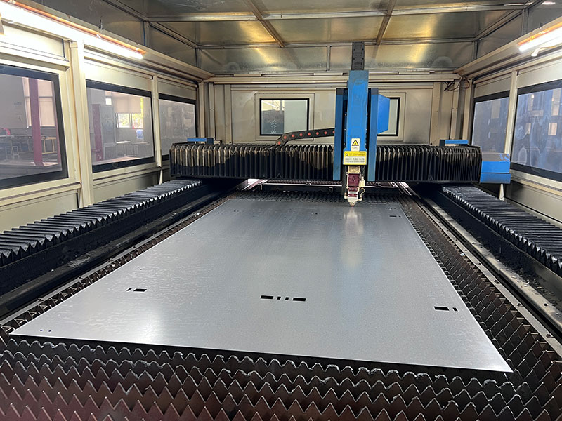
Hagoe Electric Technology Co., Ltd. operates an integrated manufacturing process covering engineering design, sheet-metal fabrication, electronic assembly, system integration, and final testing.
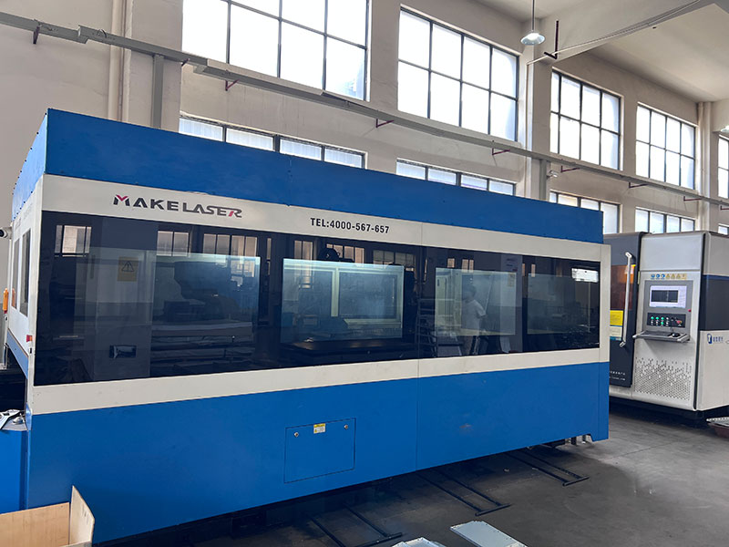
The production base is equipped with German Trumpf laser cutting machines, Japanese AMADA CNC bending machines, automated turret punching equipment, SMT production lines, and intelligent aging-test systems.
For critical power equipment such as UPS systems, quality verification must go beyond component inspection. Depending on the product configuration and project requirements, testing can include:
input/output electrical parameter verification, protection-function testing, communication testing, load testing, aging testing, and complete system functional verification.
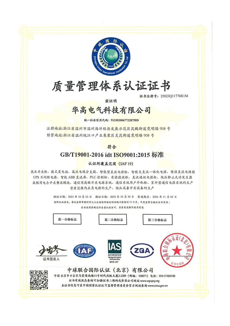
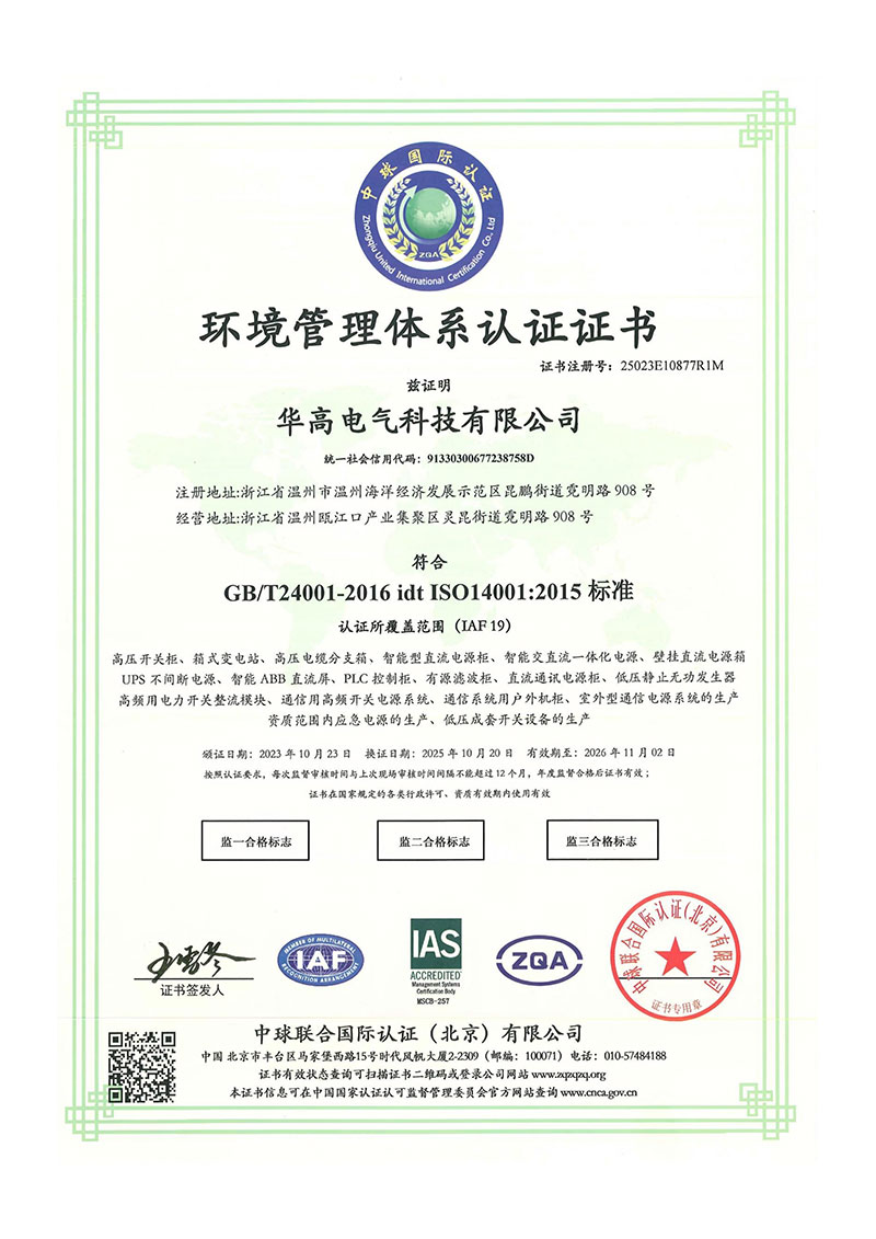
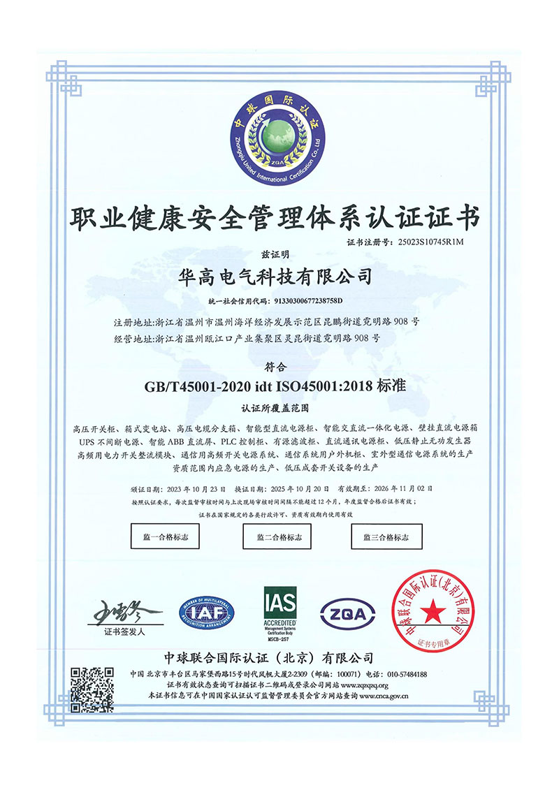
Hagoe operates under ISO9001, ISO14001, and ISO45001 management systems and holds more than 34 national patents supporting its R&D and manufacturing capabilities.
Suitable for substations, distribution systems, and power automation equipment requiring continuous power for protection, monitoring, and communication loads.
Suitable for PLCs, DCSs, industrial computers, automation cabinets, and production-line control systems.
Suitable for medical imaging, monitoring, and other precision equipment requiring stable and uninterrupted power.
Suitable for servers, network equipment, storage systems, and communication infrastructure.
HAGOE's quality control is not limited to final inspection. It covers the complete process from incoming materials to manufacturing, assembly, commissioning, testing, and final release.
The major control stages include:
Incoming Inspection → Process Control → Electrical Assembly Inspection → System Commissioning → Performance Testing → Aging Verification → Final Inspection
For customized UPS projects, HAGOE engineers can review the customer's load list, single-line diagram, installation environment, and project standards before production to reduce risks associated with capacity selection, interface configuration, and site installation.
HAGOE provides different installation and commissioning support according to equipment type and project scale.
For standard wall-mounted UPS units and small systems, HAGOE provides English installation manuals and 24/7 remote video technical support, allowing trained customer teams to complete installation with remote commissioning assistance.
For medium-sized UPS systems, distribution cabinets, and complete equipment sets, on-site installation and commissioning can be arranged according to project requirements.
For large power station and EPC projects, HAGOE develops a dedicated installation and commissioning plan before delivery and can arrange technical personnel for on-site support.
The basic information includes load capacity, actual load power, power factor, input/output voltage, frequency, required battery autonomy, load type, installation environment, bypass requirements, and communication protocol.
Motor loads can generate high starting current. The UPS therefore needs sufficient inverter overload capability and transient performance rather than being selected only according to the motor's rated running power.
Yes. HAGOE can integrate the UPS, battery system, distribution components, monitoring interfaces, bypass configuration, and related electrical equipment according to project requirements.
Yes. Input/output voltage, frequency, cabinet configuration, communication interface, protection configuration, labeling, documentation, and applicable compliance requirements can be adapted to the target market.
For EPC projects, HAGOE can participate from the technical selection stage and provide system configuration, drawings, technical documentation, production tracking, inspection documents, installation guidance, and commissioning support.
Address
No. 908, Niming Road, Kunpeng Street, Wenzhou Marine Economic Development Demonstration Zone, Wenzhou City, Zhejiang Province, China
Tel